Modular Prototyping and You
You’ve seen it in movies before—the music picks up, the engineering whiz writes down a math equation, for some reason a welder is involved; ninety seconds and a montage later, there’s a brand-new gadget sitting on the table, flawless and ready to go.
Except that’s not exactly how engineering works in the real world. More importantly, that’s not how you want things to work. The prototyping stage is vital to the design process because it’s much easier to work out kinks in the design as early as possible. You don’t want to find out that your pieces don’t fit together after you’ve made ten thousand of them.
Effective prototyping requires time and resources. This initial investment may seem unappealing because the first prototype is not a finished product, so it isn’t ready for market, and it may feel like a detour away from a polished design. And what if the first prototype doesn’t work out the way you thought? That means multiple prototypes, which means more time and more money, right?
Not quite! By designing your prototype to be modular, you can get the best of both worlds, maximizing the number of testable concepts while minimizing your time and cost.
Modularity and Industrial Design
On the industrial design side of things, where questions like “how comfortable is this grip?” and “how does this look on a shelf?” don’t have concrete answers in a reference table, prototyping is key. Ergonomic design is driven by the user, so it’s intuitive to get something into their hands as quickly as possible for early testing.
Let’s pretend that we’re developing the relatively simple handheld flashlight below:
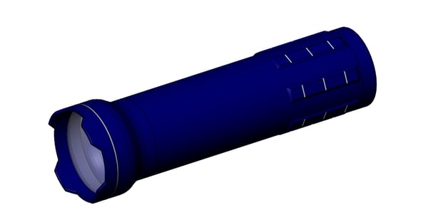
In a traditional prototyping process, you could test industrial design and engineering separately, by fleshing out handle concepts that don’t have internals while electrical development operates in parallel. However, you may be prioritizing going to market as quickly as possible—perhaps your patent is expiring, or your investors want to see a working prototype. In this case, your first prototype should allow for testing as many elements of the design as possible. This may mean splitting a part that would normally be a single piece into multiple modules, which can then be swapped out to create multiple versions of a prototype.
In production, the outer housing of this flashlight would probably have at least two assembly pieces: an endpiece with an electrical contact and the switch (red); and a piece containing the lens, LED array, and circuit board (blue). Note that the battery would constitute a third removable piece, but as this piece would be internal, it is not shown here.
Dividing this piece in such a fashion is ideal for manufacturing, as, among other things, it minimizes the risk of water ingress on the electronics, reduces the number of user-accessible breakpoints, and still allows easy access to batteries for replacing. However, if we want to test different types of grips, we will need to remake the entire blue part—which, due to the electronics, will likely be the most cost and time-intensive part of this prototype to fabricate and assemble.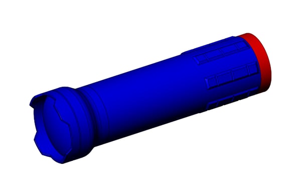
In prototyping, when minimizing part count and maximizing durability is less necessary, splitting the design into multiple pieces that can be swapped out easily lets us get around this problem. For prototyping purposes, we can make the grip section of the blue piece a separate module from the electronics and lens portion of the assembly:
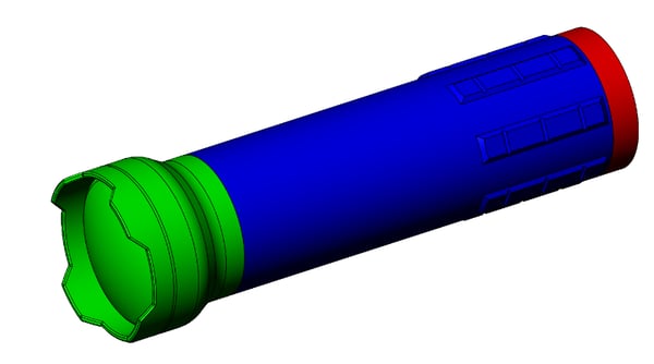
The modified blue module, which contains the grip, is much simpler and less expensive to fabricate—at this point it is effectively a hollowed cylinder with grip tabs, with no electronics assembly necessary—and we can easily make several different versions of it to test out different grips, while reusing the more complex green and red modules.
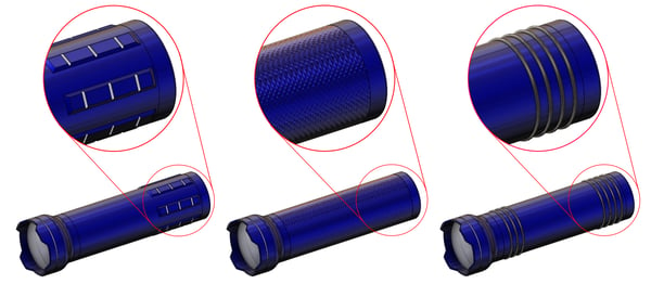
A sample overmolded rubber grip, a tab grip, and a knurled grip.
Modularity and Mechanical Engineering
Engineering is driven by calculations and data, but it’s not (always) as simple as crunching the numbers and generating results. Sourcing materials in the real world poses an additional set of difficulties. You may, for example, calculate an ideal shaft diameter only to find that it lies between two standard bearing sizes. Can the high factor of safety on your analysis be relaxed to allow for the smaller shaft size, or should you spec your design for the larger one?
Additionally, the further your design is from existing products, the less likely you’ll be able to find reference data on them. Perhaps you’re trying to design a vibrating system that requires spring mounts for dampening. Because of incomplete specifications available from vendors for your specific use-case, you intend to select springs that are in the theoretical range that you’ve calculated, but you intend to run the system to gather empirical data to compare how the spring mounts perform.
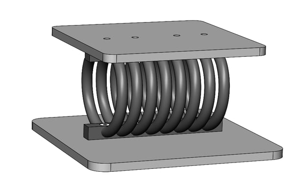
Let’s take a look at a cropped view of our system, focusing on the suspension system. Note that the design here has been dramatically oversimplified for display purposes—the actual system is quite large, and quite costly, and we do not want to make it more than once if we can help it. Our ideal suspension system should 1) dampen as much vibration as possible and 2) maintain the gap between the upper and lower plates shown below.
We’ve run vibration analyses on the system, and we’ve determined that a stiffer spring than the one initially chosen may cause us to get more desirable harmonics. However, the bolt pattern is quite different—we’ll need to add extra holes (blue) to accommodate the new hardware. The hole pattern for the original mounts are shown in red:
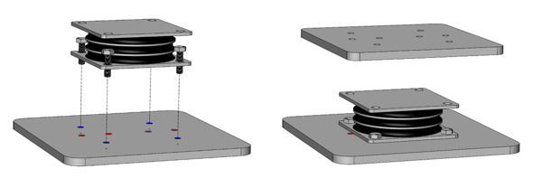
This solution lets us mount to the lower plate, but we’ve now created a gap between the upper and lower plates. In this case, the simplest solution is to design around the largest spring, and to incorporate the smaller spring with a cheap spacer. This lets us keep the geometric characteristics of the system the same in either configuration, while still allowing us to swap out vibration characteristics as desired:

We can take it one step further and help out our vibration analyst even more by introducing a spacer module that would allow us to mount the same spring at different angles. Note that we want to keep the spring symmetric around the central axis regardless of how much we rotate it, so we design the spacer module to fit around it.

A set of modular adapter blocks that allows for mounting at 5, 15, and 25 degrees.
Modularity and Finalization
As a concept, modularity is a valuable tool and also one that’s relatively easy to grasp and apply, but modular prototypes aren’t always the option. Modularity means flexibility, but it also means that you might be sacrificing other elements of the design—extra holes or hardware where it isn’t strictly necessary could be detrimental. Once testing is complete, you’ll be able to remove the modular aspects and hone in on the one configuration that performs the best.
Because of this, modular prototypes are most effective early: when you need to be testing many things at once, usually when you want to reduce cost or speed up your timeline by consolidating your lead times. It’s the design equivalent of casting a wide net, and as such it’s most valuable in the beginning phases of designing, with the goal of gathering information and data. As your design approaches manufacturing, it should become more and more refined—a product that performs a specific set of tasks very well is almost always superior to a product that performs a wide variety of tasks sufficiently.
Interested in learning more about Boulder Engineering Studio? Let's chat!
Previous Blog Posts
Finishing An Injection Molded Part |
Machining Best Practices |

|
|
.svg)


